The directional valve is a directional control valve with more than two flow forms and more than two oil ports, which is a valve that realizes the communication, cutting off and reversing of hydraulic oil flow and pressure unloading and sequential action control, and controls the direction of the relative movement of the valve core and the valve body. According to the number of working positions that the valve core stays in the valve body, it is divided into two positions, three places, etc.; According to the number of oil circuits connected to the valve body, it is divided into two-way, three-way, four-way and six-way; The operation of the valve core movement includes manual, motorized, electric, hydraulic, electro-hydraulic and other types. Directional valve, also known as Chris valve, a kind of valve, with a multi-directional adjustable channel, can change the fluid flow direction in time, can be divided into manual directional valve, electromagnetic directional valve, electro-hydraulic directional valve, etc.
Manual directional valve. The operation mode of the manual directional valve is the handle, which uses the lever principle to push the spool to move in the valve body to achieve reversing. When the handle is pulled to the left, the pressure oil P communicates with AD, the pressure oil enters the actuator, the return oil of the actuator enters the B port, and flows back to the oil tank from the T port; The actuator will move in the opposite direction.
Electric directional valve. Electric directional valve, also known as stroke directional valve, when the movement of the iron block or cam in the actuator touches the spool of the stroke directional valve, the shallow internal oil circuit changes and invests.
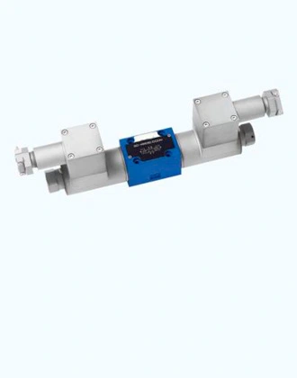
Electromagnetic reversing valve. The working principle of the electromagnetic directional valve is electromagnetic suction, after the solenoid is energized, the armature is pulled together to push the valve core to move in the valve body, the valve realizes reversing, and when it is closed after cutting, the valve is moved by the spring. The picture shows the Rexroth 4WE solenoid directional valve, which is a three-position four-way valve. When the left solenoid is energized, push the valve core to move to the right, P to B, A to T; The right electromagnet is energized, P is connected to A, and B is connected to T.
Hydraulic directional valve Hydraulic directional valve is the use of control oil acting on the valve core, when the control oil is pressurized to control the direction of the reversing valve. Hydraulic diverter valves are often used in conjunction with other diverter valves. As shown in the figure, when there is no pressure oil, the spring acts on the left end spool, P is connected to B, A is connected to T; When there is pressure oil, the valve core moves to the right, so that the four oil ports P, T, A, B are not connected.
Electro-hydraulic reversing valve electro-hydraulic reversing valve is suitable for occasions with large flow, due to the limited thrust provided by the solenoid, when the flow rate is large, the solenoid can not push the valve core, the electro-hydraulic reversing valve adopts the electromagnetic reversing valve as the pilot valve, and the hydraulic directional valve as the main valve. The flow direction of the control oil is changed by the shallow direction of electromagnetic commutation, so that the main valve is reversed under the action of the control oil. The upper end is a solenoid directional valve as a pilot valve, and the lower end is a hydraulic directional valve as the main valve. The two pilot valve oil outlets act on both sides of the main spool, and the figure shows the form of external control and leakage. The control oil X of the pilot valve is introduced from the outside and is not connected to the main oil circuit; The oil return of the pilot valve is returned to the tank separately. When the left solenoid is energized, the pilot spool moves to the right, and the X control oil enters the right side of the main spool, pushing the main spool to the left, so that the main oil circuit P is connected to A.B and T; Otherwise, when the right electromagnet is turned on, P is connected to B and A is connected to T.
The above is the working principle of the hydraulic directional valve, after purchasing the product, Elephant Fluid Power will provide each customer with free technical guidance to ensure that each customer can use the hydraulic conversion valve correctly and minimize the damage to the steering valve caused by improper operation.
Hydraulic directional valve diagram
Hydraulic directional valve troubleshooting
Hydraulic directional valve symbols
Hydraulic directional control valve types
 French
 Portuguese
 Russian
 German
 Spanish
 Japanese
 Korean
 Irish
Irish
 Greek
Greek
 Turkish
 Italian
 Danish
 Romanian
 Indonesian
 Czech
Czech
 Afrikaans
 Swedish
 Polish
 Basque
 Catalan
 Esperanto
 Hindi
Hindi
 Lao
Lao
 Albanian
 Amharic
 Armenian
 Azerbaijani
 Belarusian
 Bengali
 Bosnian
 Bulgarian
 Cebuano
 Chichewa
 Corsican
 Croatian
 Dutch
Dutch
 Estonian
 Filipino
 Finnish
 Frisian
 Galician
 Georgian
 Gujarati
 Haitian
 Hausa
Hausa
 Hawaiian
 Hebrew
 Hmong
Hmong
 Hungarian
 Icelandic
 Igbo
Igbo
 Javanese
 Kannada
 Kazakh
 Khmer
Khmer
 Kurdish
 Kyrgyz
 Latin
Latin
 Latvian
 Lithuanian
 Luxembourg
 Macedoniar
 Malagasy
 Malay
Malay
 Malayalam
 Maltese
 Maori
Maori
 Marathi
 Mongolian
 Burmese
 Nepali
 Norwegian
 Pashto
 Persian
 Punjabi
 Serbian
 Sesotho
 Sinhala
 Slovak
 Slovenian
 Somali
 Samoan
 Scots Gaelic
 Shona
Shona
 Sindhi
 Sundanese
 Swahili
 Tajik
Tajik
 Tamil
Tamil
 Telugu
 Thai
Thai
 Ukrainian
 Urdu
Urdu
 Uzbek
Uzbek
 Vietnamese
 Welsh
Welsh
 Xhosa
Xhosa
 Yiddish
 Yoruba
 Zulu
Zulu

