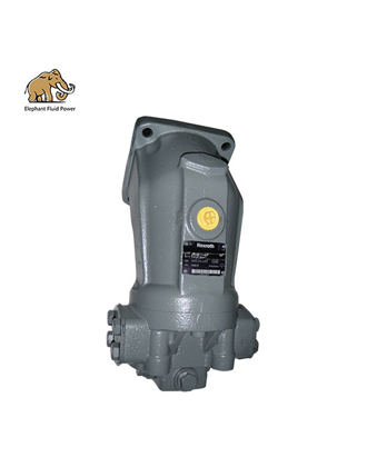
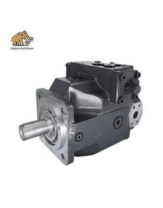
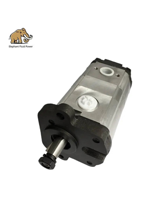
(Applicable to Elephant Fluid Power hydraulic piston pumps, piston motors and their interchangeable replacement models)
Executive Summary
This document specifies the standard operating procedures and precautions for the replacement, installation, oil filling, air bleeding, and first-time commissioning/run-in of hydraulic piston pumps and piston motors manufactured and sold by Elephant Fluid Power Co., Ltd. (Shijiazhuang, Hebei, China) — including the EFP-A10VSO series swashplate axial piston variable pumps for open circuits (sizes 10, 18, 28~140; nominal pressure 28 MPa, peak pressure 35 MPa), HMCR/HMS series radial piston motors (identical in form, mounting and function to Rexroth MCR series), and commonly used travel motors and swing motors . Elephant Fluid Power products are designed as interchangeable replacements for original imported units from Rexroth, Kawasaki, Sauer (Danfoss), Linde, Eaton Vickers, Komatsu, Hitachi, Caterpillar and others; their installation and commissioning requirements are identical to those of the corresponding OEM models. This procedure therefore also incorporates provisions from the Rexroth A2FM/A6VM commissioning manuals, the Poclain Hydraulics radial piston motor installation guide, and field service practices for construction machinery .
The core requirement can be stated in one sentence: the pump and motor must be “filled with oil first, then fully bled of air” before first start-up, and the housing must remain completely filled with hydraulic oil during start-up and operation. Numerous field cases of early failure — charge pump wear, valve plate seizure, abnormal piston/slipper wear — all originate from improper oil filling and air bleeding after replacement .
1. Scope of Application and Personnel Requirements
1.1 Scope of Application
This procedure applies to on-site replacement, installation and commissioning of the following products: Elephant Fluid Power EFP-A10VSO series open-circuit swashplate axial piston variable pumps (Size 10 Series 52, Size 18 Series 31, Size 28~140 Series 31); HMCR/HMCRE series radial piston motors (interchangeable with Rexroth MCR03/MCR05 etc., used in coal cutters, skid-steer loaders, rock breakers); HMS series motors; HVL/HVK/HVN series vane motors; and piston pumps, travel motors and swing motors interchangeable with Rexroth, Liebherr, Komatsu, Hitachi, Kawasaki, Caterpillar, Linde, Hawe, Parker, Kubota, Toshiba and Sauer models . For closed-circuit pump-motor systems (e.g., travel drives), the circuit flushing and air bleeding provisions in Chapters 6 and 7 of this procedure also apply.
1.2 Personnel Qualifications
Installation, commissioning, maintenance and repair may only be carried out by qualified personnel who are familiar with the machine’s functions and safe operation; the Elephant Fluid Power catalogue explicitly states: “Only qualified personnel who are familiar with the machine function and safety operation are allowed to maintain the machine” . Personnel must read the product catalogue for the specific model and the machine manufacturer’s service manual before work, verify the technical data (pressure, speed, direction of rotation, port sizes and tightening torques), and be trained in safe working with hoisting, overhead loads and pressurized hydraulic systems.
1.3 Basic Safety Requirements
The following safety confirmations are mandatory before any hydraulic system service work: shut down the machine and release all system pressure (including accumulators); post “Do Not Start” warning signs and apply lockout/tagout (LOTO). Immediately after shutdown, the pump/motor housing and solenoids remain very hot and present a burn hazard — wear protective clothing, gloves and safety glasses before touching components . A pressurized jet of leaking hydraulic fluid can penetrate skin and cause severe injury — never use hands or rags to locate or plug leaks; wash skin promptly after contact with hydraulic fluid and seek immediate medical attention if fluid enters the eyes 1. Use lifting equipment with adequate capacity margin (recommended rated capacity no less than 120% of component weight) when handling heavy components, and never stand under suspended loads .
2. Replacement Procedure (Removal of the Old Unit)
2.1 Preparation Before Removal
Before replacing a piston pump or motor, verify that the part number/ordering code of the new unit matches the machine manufacturer’s recommended model, confirming that the direction of rotation, displacement, control mode (e.g., DR, DRG, DFR1), mounting flange (SAE 2-bolt / ISO 2-bolt) and shaft end (keyed/splined) are identical to the original. The Elephant Fluid Power EFP-A10VSO ordering code corresponds to the Rexroth A10VSO system; for example, EFP-A10VSO 18 DR/31 R-PSC12K52 denotes clockwise rotation, NBR seals and an SAE splined shaft . Prepare a drip tray, clean plugs/caps, lint-free cloths, a torque wrench, an oil filling unit (10 μm filtration) and sufficient hydraulic oil meeting the specified requirements.
The working environment for disassembly must be clean and dust-free. Internal components of hydraulic units are hardened and precision-fitted (piston-to-bore clearances are measured in microns); any fine debris or fibers entering the unit can cause sticking, scoring and abnormal wear. Therefore never wipe internal cavities with cotton rags — use lint-free cloths and mild cleaning agents, and keep the work area free of metal chips, sand, dust and water .
2.2 Removal Steps for the Old Unit
1. Depressurize and drain: After shutdown and pressure release, place a drip tray under the pump/motor. Disconnect the case drain line first, then the working lines, allowing oil in the lines and housing to drain out for recovery.
2. Cap all ports: Immediately plug the open ports of the removed unit and the system with clean caps to prevent contamination; protective caps on the new unit must not be removed until immediately before connecting the lines .
3. Protect mating surfaces: Do not strike the drive shaft, seal mounting surfaces or sensitive components (sensors, control valves, solenoids); never use the pump/motor as a handle or step, and do not place objects on it .
4. Record the configuration: Record and photograph the mounting orientation of the old unit, port-to-line assignments and line routing as a reference for installing the new unit.
2.3 System Cleaning and Flushing (Critical to Replacement Success)
When a pump or motor fails due to wear or seizure, the metal particles and debris it generates contaminate the entire hydraulic system. Replacing only the failed unit without flushing the system will destroy the new unit within tens of operating hours. System-level cleaning is therefore mandatory:
• Oil change and filtration: Inspect the oil in the reservoir. If it contains metal particles, water or excessive acidity, replace it entirely with new oil; never reuse old, unfiltered oil 4. Even new oil as delivered usually does not meet the required cleanliness class — always fill through a filtration unit 1.
• Replace filter elements: Replace all suction, pressure and return-line filter elements; check the filter clogging indicators closely during the first 50~100 hours after break-in of the new unit, and perform the first filter change at 50/100 hours .
• Flush the circuit: Thoroughly flush the hydraulic circuit before first start-up. For open circuits, collect contaminants through the return filter or a temporary 10 μm (non-bypass) filter ahead of the reservoir. For closed circuits, install 10 μm absolute filters in the high-pressure return lines near each pump and set up a temporary bypass flushing loop at the motor ports; replace the filters after flushing and before commissioning .
• Pre-flush the new motor: If the new motor is shipped filled with rust-preventive/storage oil, drain and flush it with a neutral flushing fluid compatible with the system oil before installation: place the motor horizontally, drain the storage oil through the supply port, drain port, brake port and displacement control port; fill the housing and cavities with flushing fluid and drain again, repeating several times. Then run the motor in an open loop at 8~10 rpm for 2 minutes in each direction (maintain 2~5 bar return back-pressure), drain the flushing fluid completely, flush several times with system oil, and only then install 1. Never mix hydraulic fluids from different manufacturers or of different types .
3. Installation Procedure
3.1 Mechanical Installation
A flexible coupling is recommended between the piston pump and the drive motor/engine, with shaft alignment error not exceeding 0.2 mm. Transmission arrangements that impose shock or radial loads (e.g., universal joints) must not be used; never hammer the coupling during assembly/disassembly, and never force splined connections together . For belt drives, verify the permissible radial force on the drive shaft (e.g., EFP-A10VSO size 10: permissible radial force 250 N, axial force 400 N); mount the belt pulley on a separate support if necessary . The pump mounting bracket must be sufficiently rigid, and long pipelines must be secured with supports to prevent vibration. To reduce noise, all connecting lines (suction, pressure, drain) should be decoupled from vibrating components such as the reservoir using elastic elements .
When mounting a motor, the mounting flange and machine frame mating surfaces must be clean, flat and perpendicular to the motor axis; tighten the mounting bolts in a cross pattern in stages to the specified torque (verification per VDI 2230 recommended). For radial piston motors mounted with a torque arm, the counter-torque arm length must not be shorter than the specified minimum R, and the arm end must retain two degrees of freedom (a ball-joint linkage is recommended) to avoid additional bearing loads 1. For wheel-hub motors, tighten the rim nuts in a criss-cross pattern to the specified torque without lubricating the bolts and nuts, and re-check after 40 km and 100 km of travel .
3.2 Mounting Position and Port Connections
The mounting position largely determines the oil filling and air bleeding procedure. Whether mounted horizontally or vertically, it must be ensured that the pump/motor housing is filled with oil before start-up and remains completely filled during operation . The core rules are as follows:
Item | Requirement |
|
Case drain port | The housing must be drained through the highest-positioned drain port; where two drain ports exist, connect the upper one to the return line and plug the lower one |
|
Drain line | Line size must match the port; no check valve is permitted in the drain line (exception: when mounted above the reservoir with shaft pointing up, a 0.5 bar check valve may be fitted to prevent housing drainage); suction and drain lines must extend below the minimum oil level in the reservoir under all operating conditions to prevent air ingestion and foaming |
|
Case pressure | EFP-A10VSO: max. permissible case drain pressure is 0.5 bar above suction port S, not exceeding 2 bar absolute (for servo-controlled variable pumps, case pressure above 0.15 MPa impairs the sensitivity of the stroking mechanism — special attention required) |
|
Suction conditions | EFP-A10VSO: absolute pressure at suction port S 0.8~30 bar; boost (charge) supply at 0.2~0.4 MPa is required at and above nominal speed, with charge pump flow no less than 120% of main pump flow |
|
Shaft-up mounting | When mounted vertically with the shaft pointing up, additional flushing/lubrication must be provided through the bearing flushing/air bleed port (e.g., port U on A6VM, flushing option B on Poclain motors) to prevent inadequate lubrication of the front bearing and shaft seal |
|
Mounting above reservoir | When the pump is mounted above the minimum reservoir level, permissible suction lift is related to total line pressure loss (total loss on the order of 0.2 bar max.); avoid mounting the pump above the reservoir where low noise is required |
|
In closed circuits, an air bleed port should be provided at the highest point of the piping; the low-pressure side must be maintained between 15 and 30 bar; cavitation conditions of 0 bar at either high-pressure port are strictly prohibited .
4. Hydraulic Fluid Requirements and Oil Filling Procedure
4.1 Fluid Type, Viscosity and Cleanliness
Item | Specification | Source |
Fluid type | Mineral oil: HM for stationary equipment, HV for mobile equipment (ISO 6743-4, category H); consult the manufacturer for environmentally acceptable or fire-resistant fluids |
|
Optimum operating viscosity | 16~36 mm²/s (referred to reservoir temperature, open circuit) |
|
Viscosity limits | Short-term peak 10 mm²/s (leakage oil up to 90 °C short-term); cold start 1000 mm²/s |
|
Temperature range | -25 °C to +90 °C; recommended operating oil temperature 16~65 °C |
|
Cleanliness class | Open circuit: at least ISO 4406 18/15 (NAS 1638 class 9); closed circuit / Rexroth requirement: ISO 4406 20/18/15; at oil temperatures of 90~115 °C, improve to 19/17/14 |
|
Pressure-line filter | Filtration rating 10~25 μm with clogging indicator; suction strainer 120 μm; reservoir breather 10 μm |
|
4.2 General Oil Filling Rules
Oil filling must be performed using a filling unit with 10 μm filtration (filter cart/filling device); do not operate the pump/motor during filling . Place a drip tray under the component to collect spillage before filling. Oil as delivered usually does not meet the component cleanliness requirements and must be filtered during filling 2. Before filling the reservoir, clean it and confirm it is free of metal particles, sand and water; keep the oil level above the minimum mark. If the high-pressure lines are long and hold a large volume, pre-filling of the high-pressure lines is recommended .
4.3 Pump Housing Filling Steps (Mandatory at First Start-up or After Replacement)
Before first start-up, the pump housing must be completely filled with clean hydraulic fluid through the housing filling port / highest drain port — this is the decisive step that prevents dry-friction seizure of the valve plate, slippers, pistons and bearings. Field failure statistics show that failure to fill or inadequate air bleeding directly causes low charge pressure, filter clogging by metal particles, port plate wear and severe piston/slipper wear .
1. Remove the plug from the highest-positioned drain/filling port of the pump housing (the EFP-A10VSO has two drain ports L and L₁);
2. Fill the housing through this highest port using the filling unit, until oil overflows from the port;
3. If space constraints prevent filling from the highest point and filling must be done through a lower port, the plug at the highest port must be opened at the same time; once oil overflows from the highest port, keep the level in the filling line above the internal oil level of the pump before refitting the plugs ;
4. Turn the pump shaft by hand 3~4 revolutions to confirm free, smooth rotation without binding, allowing oil to reach all friction pairs ;
5. Re-tighten the plugs / reconnect the drain line and wipe off any external oil traces.
4.4 Motor Housing Filling Steps
1. Fill the motor housing with clean, filtered hydraulic fluid through the uppermost drain port; for radial piston motors (HMCR type, Poclain MS/MCR type), loosen the uppermost air bleed screw, fill with the filling device, and re-tighten the bleed screw to the specified torque once oil flows out (Poclain specifies 5/+1 N·m) ;
2. For motors mounted vertically (shaft pointing up), ensure the front bearing and shaft seal are lubricated — a gooseneck in the drain line may be used to raise the oil level in the housing ;
3. Motors equipped with an internal flushing device will be filled automatically during test runs; the hydraulic lines of the system must also be filled ;
4. After filling, confirm that all ports have been reconnected or plugged .
5. Air Bleeding Procedure
5.1 Why Air Bleeding Is Necessary
Air trapped in the system causes cavitation, noise, vibration, jerky (stick-slip) actuator motion and sluggish response, and leads to inadequate lubrication and early failure of internal pump/motor components — damage that often does not appear immediately but surfaces as component failure after several hours of operation 1. Therefore, before no-load and on-load testing, the pump, motors, cylinders and the entire circuit must be thoroughly bled of air. After long shutdown periods (e.g., seasonal storage), air bleeding must be repeated before re-commissioning, since air may accumulate and housings may drain back through the lines during standstill .
5.2 Hydraulic Pump Air Bleeding Steps
1. Loosen the air bleed plug on the pump body (or regulator); once oil seeps out continuously (bubble-free), tighten the plug — for excavator main pumps, the bleed plug tightening torque is typically 7.8~9.8 N·m ;
2. If no oil seeps from the bleed plug, the pump housing is not full: disconnect the case drain line and refill the housing through the drain port until full (while the drain line is disconnected, keep its open end above the reservoir oil level to prevent siphoning back), then tighten the bleed plug and refit the drain line ;
3. After bleeding, start the engine and run it at low idle for 10 minutes without applying any load ;
4. Closed-circuit systems: start the charge (auxiliary) pump first to expel air from the lines and adjust the charge relief valve to the specified supply pressure (0.3~0.7 MPa), then start the main pump .
5.3 Hydraulic Motor Air Bleeding Steps
1. Housing bleeding: Loosen the uppermost air bleed screw on the motor → supply oil → once oil flows out continuously without bubbles, stop the supply and re-tighten the bleed screw to the specified torque (Poclain specifies 5/+1 N·m); collect spillage in a drip tray ;
2. Travel motors: With the engine at low idle, loosen the travel motor air bleed plug; once oil seeps out, tighten it (typical tightening torque 27.5~35.3 N·m) ;
3. Swing motors: With the engine at low idle, slowly rotate the upper structure so that air is carried out with the circulating oil ;
4. Variable motors mounted shaft-up: the housing must be additionally bled through flushing port U; in other mounting positions the housing bleeds automatically via the drain line ;
5. Motors with parking brake: the brake control chamber must also be bled — loosen the brake air bleed screw, supply oil until oil flows out, then re-tighten (5/+1 N·m) .
5.4 Circuit and Cylinder Air Bleeding Steps
1. Jack up the machine so the wheels are clear of the ground (or ensure the motor carries no load) ;
2. After starting the engine, run at low idle for at least 30 seconds to let air escape from the pump side; check the reservoir oil level and top up ;
3. Operate the motor slowly in both directions, gradually increasing speed to 10%~20% of normal speed, to expel air from the high-pressure lines (closed circuits bleed via the flushing valve; open circuits bleed through oil circulation); check and top up the reservoir level again ;
4. Cylinder bleeding: after the engine has run at low idle for 5 minutes, raise and lower the boom slowly 4~5 times (stopping about 100 mm before stroke end, without applying relief pressure), then repeat at high idle; finally, at low idle, extend the piston rod to the stroke end and apply relief pressure. Bleed the arm and bucket cylinders in the same manner. For newly replaced cylinders, bleeding before mounting to the work equipment is recommended .
6. First Start-up, Run-in and Functional Testing
6.1 First Start-up Procedure
1. Pre-start checks: verify the part number; check the mechanical installation, output shaft connections and tightness of all line connections (to prevent leakage and air ingress); check the condition of all hoses; reservoir clean with correct oil level; pump/motor housings filled with oil; relief valves preset to a relatively low pressure (but not to the minimum setting) 1;
2. Variable displacement settings: for pump operation, set the displacement to minimum first; for motor operation, set it to maximum; then adjust gradually to the required operating condition ;
3. Jog / low-speed no-load operation: start at low speed without load; listen for noise and check for leaks. Increasing noise (a sign of cavitation) or air bubbles in the case drain oil indicate insufficient oil supply — shut down immediately and repeat filling and bleeding ;
4. Gradual loading: increase the load step by step and verify that the operating pressure rises as expected; perform a leakage test to confirm the system is tight at maximum pressure; at maximum pressure, verify that the case drain pressure does not exceed the permissible value ;
5. Run-in operation: a new pump, or one after long storage, should run in at a low pressure of about 2.5 MPa for 1~2 hours; afterwards set the relief valve to 110%~120% of the system working pressure .
6.2 Run-in Period Restrictions
Newly installed or overhauled pumps/motors are in a run-in period during the first approximately 10 hours, during which friction between mating parts generates metal and plastic particles; the following derating requirements apply :
Restricted Item | Run-in Period Limit |
Operating power | 50% of max. permissible power |
Operating speed | 50% of max. permissible speed |
Operating pressure | 65% of max. permissible pressure |
During the run-in period (first 50~100 hours), closely monitor the filter clogging indicators and perform the first filter element change after 50/100 hours of operation .
6.3 Operating Limits
Operating pressure and speed must not exceed the values on the nameplate. Continuous operation at peak pressure must not exceed 1 minute; the cumulative time at peak pressure in intermittent operation must not exceed 10% of total operating time . Taking the EFP-A10VSO as an example: nominal pressure 28 MPa (280 bar), peak pressure 35 MPa (350 bar); for size 10, maximum speed is 3600 rpm (up to 4300 rpm with increased inlet pressure or reduced displacement) . During operation, check leakage regularly; upon abnormal leakage, temperature rise, noise or vibration, stop immediately — stop the main pump first, and shut down the auxiliary pump only after the main pump has come to rest .
7. Summary of Precautions and Prohibitions
7.1 Critical Prohibitions (Red Lines)
• Never start without filling: before starting a pump that is being used for the first time or has been disassembled, the housing must be filled with oil and the shaft turned by hand; pumps/motors must also be re-filled and re-bled after long shutdowns, since the housing may have drained back through the lines .
• Never run dry: piston pumps/motors must not be operated with insufficient hydraulic fluid; where shut-off valves are fitted in the reservoir lines, confirm the valves are open before start-up .
• Never start with the discharge valve closed; avoid prolonged operation at zero displacement .
• Never mix hydraulic fluids from different manufacturers or of different types; remove the storage/preservation oil from components before installation .
• No check valve in the drain line (except the 0.5 bar anti-drain valve for shaft-up, above-reservoir mounting) .
• Never fit check valves/lift valves in the pilot line between the charge pump and the pilot valve, and do not use pilot valves with built-in check valves .
• Never disconnect fittings under pressure or plug leaks with rags; never hammer couplings, shaft ends or housings .
7.2 General Precautions
• Keep the work area, tools and components clean during all assembly/disassembly work; use proper tools for spring retaining rings; never use cotton rags for cleaning .
• Pipelines must pass a pressure test (test pressure = 2× working pressure) and be pickled (and preferably phosphated) before use .
• Remove protective caps from new units only when connecting the lines; mixing up ports causes wrong movements (e.g., lowering instead of lifting) — always verify the piping against the hydraulic schematic before functional testing .
• Tighten all threaded plugs and fittings to the manufacturer’s specified torque; never exceed the maximum permissible tightening torque of threaded ports (e.g., for DIN 3852: M14×1.5 port max. 80 N·m, plug 35 N·m; M22×1.5 port max. 210 N·m, plug 80 N·m) .
• For long-term storage, drain the working fluid from pumps/motors, fill with low-acid rust-preventive oil and seal all ports; storage oil must be drained and the unit flushed with neutral flushing fluid before use .
• Dispose of waste oil and cleaning agents in accordance with environmental regulations; use drip trays when filling/draining and treat spillage with absorbent material .
7.3 Regular Inspection Items (Per Elephant Fluid Power Catalogue)
Inspection Item | Requirement |
Reservoir oil level | Check regularly; keep above the minimum level |
Operating temperature | ≤ 60 °C (routine monitoring) |
Hydraulic fluid condition | Observe color and smell; periodically test for water, mechanical impurities and acid value; change oil if limits are exceeded |
Operating pressure, accumulator pre-charge | Verify periodically |
Leakage at pumps, valves and piping | Correct any abnormal leakage immediately |
Filter element cleanliness | Check clogging indicators; replace elements on schedule |
Hoses | Check for aging and blistering; replace suspect hoses |
(Compiled from the “Maintenance / Regular Check” section of the Elephant Fluid Power EFP-A10VSO catalogue .)
8. Warning: Consequences of Non-compliant Practice
Actual service cases demonstrate that when a large-displacement (250-class) axial piston pump was commissioned after replacement without correct oil filling and air bleeding, the main pump charge pressure remained persistently low; disassembly revealed the main pump filter clogged with large amounts of metal particles, port plate wear, severe piston/slipper wear and a badly damaged charge pump — different failure symptoms, the same root cause: inadequate oil filling and air bleeding before start-up . The essentials of correct practice are: “fill from the highest point, fill until overflow, turn the shaft by hand to confirm, then run in at low pressure and idle speed.” Omitting any one of these steps can destroy a new unit within hours. All provisions of this procedure should be executed with the machine manufacturer’s service manual and the product catalogue of the specific model as the final authority.
This document is compiled from the Elephant Fluid Power product catalogue and publicly available technical documents of interchangeable OEM models (Rexroth, Poclain, etc.) for field reference. For model-specific torques, pressures and port locations, the product catalogue supplied with the unit and the machine manufacturer’s manual shall prevail. This content is for general informational purposes only and does not constitute professional technical advice; all work should be performed by qualified hydraulic specialists.
 French
 Portuguese
 Russian
 German
 Spanish
 Japanese
 Korean
 Irish
Irish
 Greek
Greek
 Turkish
 Italian
 Danish
 Romanian
 Indonesian
 Czech
Czech
 Afrikaans
 Swedish
 Polish
 Basque
 Catalan
 Esperanto
 Hindi
Hindi
 Lao
Lao
 Albanian
 Armenian
 Azerbaijani
 Belarusian
 Bengali
 Bosnian
 Bulgarian
 Cebuano
 Chichewa
 Croatian
 Dutch
Dutch
 Estonian
 Finnish
 Galician
 Georgian
 Haitian
 Hebrew
 Hmong
Hmong
 Hungarian
 Icelandic
 Javanese
 Kazakh
 Khmer
Khmer
 Latin
Latin
 Latvian
 Lithuanian
 Luxembourg
 Macedoniar
 Malagasy
 Malay
Malay
 Maltese
 Maori
Maori
 Mongolian
 Burmese
 Nepali
 Norwegian
 Pashto
 Persian
 Punjabi
 Serbian
 Sinhala
 Slovak
 Slovenian
 Somali
 Samoan
 Tajik
Tajik
 Thai
Thai
 Ukrainian
 Uzbek
Uzbek
 Vietnamese
 Welsh
Welsh
 Yiddish
 Yoruba